Gas spring and its operation
A gas spring consists of a steel cylinder containing gas (nitrogen) under pressure and a rod which slides in and out of the cylinder through a sealed guide.
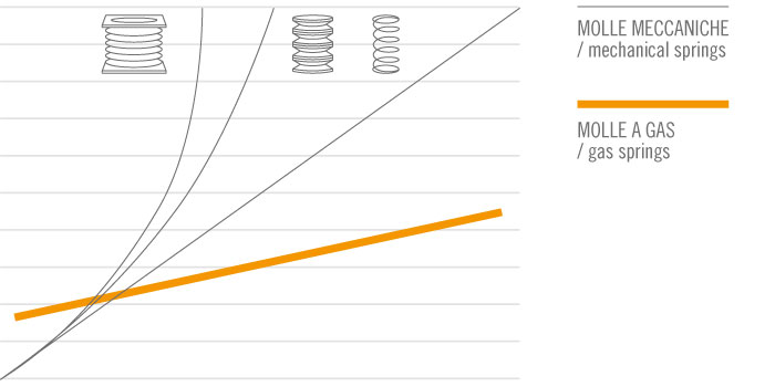
When the gas is compressed by the retraction of the rod, it produces a force in return, acting like a spring. Compared to traditional mechanical springs (whether helicoidal, Belleville washers or rubber), the gas spring has an almost flat force curve even for very long strokes. It is therefore used wherever a force is required that is in proportion to the weight to be lifted or moved, or to counter-balance the lifting of movable, heavy equipment.
The most common applications may be seen on car doors, on protective casings of industrial machines, on furniture doors, in medical and fitness equipment, on motor- driven blinds and canopies, on bottom-hinged dormer windows and inside supermarket sales counters.
In its simplest version the gas spring consists of a cylinder (C) and a piston rod (S), on the end of which a piston (P) is anchored, which accomplishes cycles compression and extension of the cylinder (C) through a sealed guide. The cylinder contains nitrogen gas under pressure (see arrows) and oil (O). During the compression phase the nitrogen passes from below the piston (B) to the upper part (A) through channels (F).
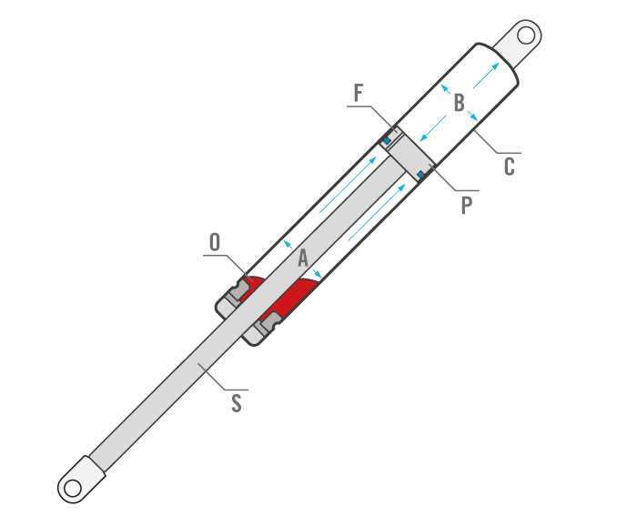
During this phase the pressure inside the cylinder, due to the low volume available caused by the entering of the piston rod, is rising generating the force increment (progression). By varying the cross section of the channels (F) the gas flow may be adjusted to slowing down or to speed up the rod sliding speed; changing the combination of cylinder/piston rod diameters, the lenght of cylinder and the oil quantity the progression can be changed.
Temperature
Temperature influences the force of a gas spring.
It makes the nitrogen in the cylinder expand or contract and, since the variation occurs at a constant volume, this causes the internal pressure to increase or decrease. The gas spring force varies by 0,36% of each °C (it means 3,6% every 10°C).
Example: considering a standard exercise temperature of 20°C and a force of 100N, at 30°C F1=103,6N and so on.
Braking action
A certain quantity of oil is introduced into the gas spring cylinder: it not only serves to lubricate the seal, but when spread between piston and guide exerts a slowing-down action during rod extension and ensures a more gentle and joltless movement. For example in the dampers range the oil braking action slow down the downward opening movement of a flap. (in these cases the nitrogen may not be used).

In the horizontal applications, applications where the piston rod is in a higher position than the cylinder (not suggested), applications where the gas spring overturn (i.e. hatchback of a car) the braking action is not present (piston do not meet the oil). The braking action in these cases has to be reached with an alternative product (Dynamic Damping Gas Spring).
The force of the gas spring
The force of a gas spring is determined by the pressure that the nitrogen in the cylindrical cylinder exerts on the section of the rod.
By assembling rods of different dyameters with cylinder of suitable volume, by acting on the gas input pressure and adjusting the channels on the piston or by introducing a greater quantity of oil, various operating configurations of the gas spring may be obtained in addition to the required force in order to satisfy a wide range of user requirements.
The force of the spring (F1) is measured with a special dynamometer at a room temperature of approx. 20 °C with the rod compressed by about 10 mm and free from friction by the seal; the measure is given in N (Newton) and it is a static (FS) value normally referred to when defining the characteristics of a spring.
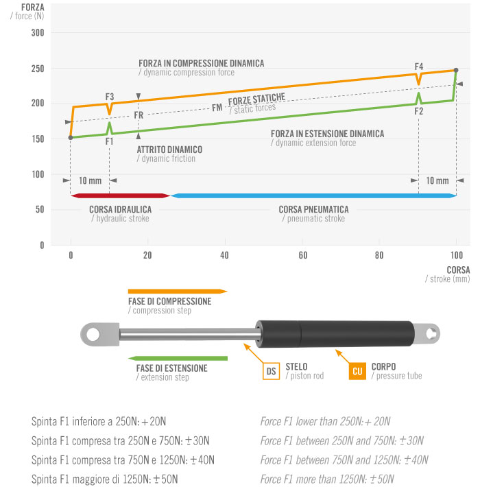
Other components interact with this basic value and become especially noticeable in the “dynamic” phase of the spring. The resistance exerted by such friction acts in the opposite direction to the rod movement, it has a value that can vary form 20 to 50 Newton and is added or subtracted to the above-mentioned “static” force. This difference is called friction and is indicated wih FR.
The closing force is indicated in the graph by F3 and the opening force by F1. It can be seen that F3 and F1 are higher and lower respectively than the average line which identifies the “static” force FM. The difference between F3 and F1 is the friction FR. The difference between F2 and F1 is the progression of the gas spring.
Calculation of the force
Formula to calculate the force of a gas spring in relation to the application
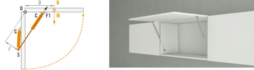
F1={[( M x D) : L] : nm } + (10% ~ 15%)
F1: Force of the spring which opposes the weight of the object to be moved, shown as vector; in this case, F1 is expressed in kg and have to be transformed in Newton multiplying the value obtained by 9.81.
M: Weight in kg of the object to be lifted, shown as vector.
D: Distance in mm measured horizontally between the center of gravity B and the point of rotation O.
B: Point of application of the weight of the object to be lifted; it corresponds to the center of gravity.
O: Fulcrum and point of rotation of the mobile object.
L: Length in mm of the gas spring working arm; it corresponds to the least distance between attachment S or attachment C and the center of rotation O; most of the time it is equal to the stroke of the gas spring and in any case cannot be greater.
S: Point of attachment of the gas spring to the fixed part.
C: Point of attachment of the gas spring to the mobile part.
nm: Number of gas springs to be used in the application (1, 2 or more).
An increase of 10-15% is included in the formula, since the force vector of the spring is not parallel to the direction of the weight vector of the object to be lifted and also to compensate for any friction in the system which would detract from the efficiency of the spring force.
Examples
Example 1
In this example (typical application: lifting of cabinet and compartment doors) point S should be placed 30/40 mm away from the cabinet/compartment border to prevent the door from slamming when it closes.
Example 2
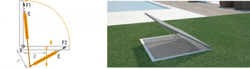
In the so called “horizontal” applications (trapdoors, crate covers, etc) the attachment point S must allow the spring to maintain in the fully closed position a downwards tilt of at least 10° to make the most of the spring also in preventing the door/cover from slamming.
In this case the F1 shall refers to the gas spring in its fully closed position i.e. F2. For this reason the result have to be divided by progression factor. Moreover in this case the increase of 10/15% is not necessary
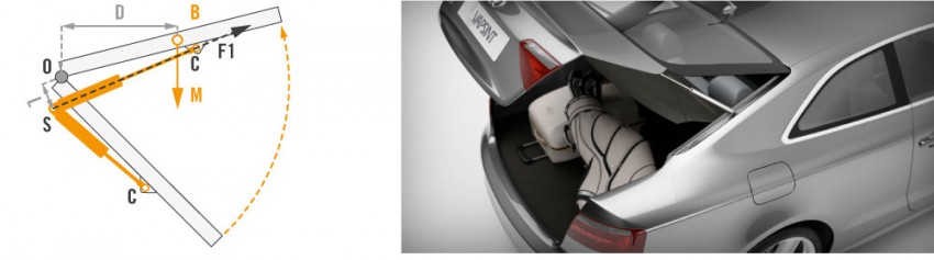
Example 3
In this example (typical application: car boots) the figure shows the spring with the rod directed upwards. The application is correct because the spring, when the boot is closed, has the rod directed downwards.
Tips for a correct installation
The gas spring long life is a function of the correct lubrication of the seals. The spring must therefore always be installed with the rod directed downwards or with the rod guide in a lower position with respect to the cylinder attachment.
In some applications, as those described in figures above (e.g. car boots), the opening movement of the spring may cause it to rotate upwards between the fully open and fully closed position. Here also attention should be paid to installing the spring with the rod directed downwards when it is in its fully closed position, and compressed inside the cylinder. Such recommended position facilitates the lubrication of guide and seals, while delivering an excellent braking effect.
The rod surface is important for maintaining gas pressure and should therefore not be damaged by blunt or abrasive objects or by any corrosive chemical substance. When installing the gas spring, the upper and lower fittings should be aligned so that the seal is not under strain. The alignment must be maintained throughout the entire rod stroke. Should that not be possible, use jointed attachments which allow the alignment.
Vibrations on the machine to which the gas spring is applied may be discharged onto the seals through attachments that are connected too rigidly to the frame. Leave a small clearance between the fixing screws and the attachments or fix the spring using at least one jointed attachment.
We recommend fixing the spring using smooth pins and not threaded bolts as the thread crest, in contact with the attachment hole, exercises friction that may contrast the gas spring correct functioning.
When applying the gas spring, make sure the pulling forces are not greater than the gas spring thrust force, so that the normal rod sliding speed is not exceeded.
The normal operating temperature for a gas spring ranges between -30 °C and + 80 °C.
Particularly damp and cold environments may create frost on the seals and compromise the gas spring duration.
The gas spring has been designed and manufactured to lighten or counter-balance a weight that is otherwise very heavy for the operator or for the structure into which it is inserted. Any other use it may be put to (shock absorber, decelerator, stop) should be carefully assessed by the designer and the manufacturers with regard to durability of the spring and to safety.
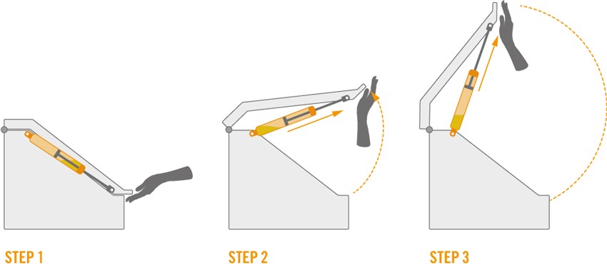
Correct application
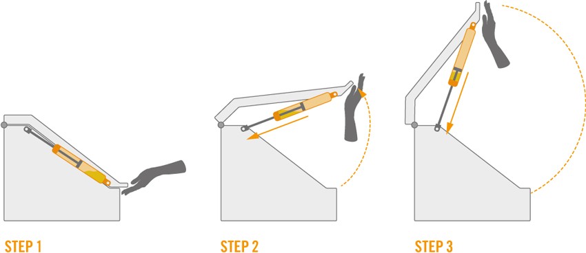
Wrong application
Disposal of the product at the end of its useful life
Warning: gas spring cylinder contains nitrogen under pressure!
The pressure inside a new gas spring can reach very high values, therefore gas spring cylinders must not be cut with jigsaws, chisels or chip removal machines as they might explode, with consequent ejection of splinters, and seriously injure whoever happens to be nearby. To dispose of gas springs the following procedure must be followed.
Procedure for the disposing of gas springs
Make sure you can rely on adequate face and hand protections;
Examine the gas spring to be disposed of, and make sure the rod is fully out of the cylinder; after fixing it safely on a drill vice, proceed to drill the cylinder using a tip measuring 1-2 mm in diameter (any smaller tip, if it breaks, may be ejected out by the gas as it comes out of the hole);
The cylinder must be drilled at a distance of about 5 mm from the lower attachment;
Drill slowly so you can get rid of shavings; as soon as you make a hole in the cylinder wall, the gas contained in it will come out quickly. Since the gas spring may contain oil, pay special attention to oil mists;
The guide contains two seals creating a small airtight enclosure that may contain gas under pressure; drill also in this area taking the same precautions as above;
Lastly, discharge the oil contained in the cylinder into proper containers to be disposed of by competent authorities or in suitable sites according to current national regulations.
 Necessari
 Funzionali
 Statistiche
 Marketing